
Introduction
In electrical power distribution design, engineers frequently use a unifilar diagram (also called a single-line diagram) to represent how equipment is connected within a power system.
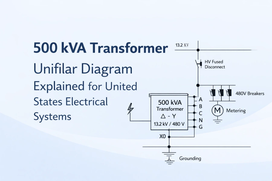
For facilities that require a 500 kVA distribution transformer, the unifilar diagram provides a simplified overview of the electrical network, including the medium-voltage supply, transformer connections, protection devices, grounding system, and low-voltage distribution.
In the United States, transformer installations usually follow ANSI, IEEE, and DOE efficiency standards, and typical voltage configurations include 13.2 kV / 12.47 kV primary voltage and 480Y/277V secondary voltage.
This guide explains how a 500 kVA transformer unifilar diagram is structured, what components it includes, and how it is used in real commercial and industrial power systems.
What Is a Unifilar Diagram in Power System Engineering
A unifilar diagram is a simplified representation of an electrical power system that uses one line to represent three-phase conductors.
Instead of drawing each individual phase, the diagram shows the functional relationships between equipment.
Engineers use unifilar diagrams for:
-
Electrical system planning
-
Substation design
-
Transformer installation
-
Protection coordination
-
Maintenance documentation
For transformer installations, a unifilar diagram normally illustrates:
-
Utility incoming feeder
-
Medium-voltage switching equipment
-
Transformer capacity and connection type
-
Surge protection devices
-
Grounding configuration
-
Low-voltage distribution panels
Because of its simplicity, the unifilar diagram is one of the most important documents in electrical engineering design.
Typical Voltage Configuration for a 500 kVA Transformer in the United States
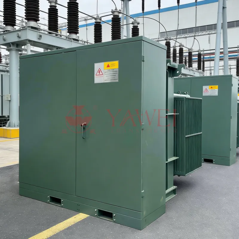
In North American distribution networks, a 500 kVA Pad Mounted transformer is commonly used to step down medium voltage from a utility feeder to low voltage for building loads.
Primary Voltage (Medium Voltage)
Common primary voltages include:
-
12.47 kV
-
13.2 kV
-
13.8 kV
-
34.5 kV
These voltages typically come from a utility distribution line or substation feeder.
Secondary Voltage (Low Voltage)
The most common secondary configuration is:
480Y / 277 V, three-phase, four-wire
This system allows:
-
480 V for motors, HVAC equipment, and industrial machinery
-
277 V for commercial lighting systems
Other possible secondary voltages include:
-
208Y / 120 V
-
240 V
-
600 V (less common in the U.S.)
Typical Connection Type for a 500 kVA Transformer
Most distribution transformers used in commercial buildings use a Delta–Wye (Δ–Y) connection.
Advantages of Delta–Wye Configuration
-
Provides a stable neutral point for grounding
-
Supports three-phase and single-phase loads
-
Reduces the impact of harmonics
-
Improves system reliability
The grounded neutral point (X0) allows safe distribution of 277 V lighting loads and provides proper fault protection.
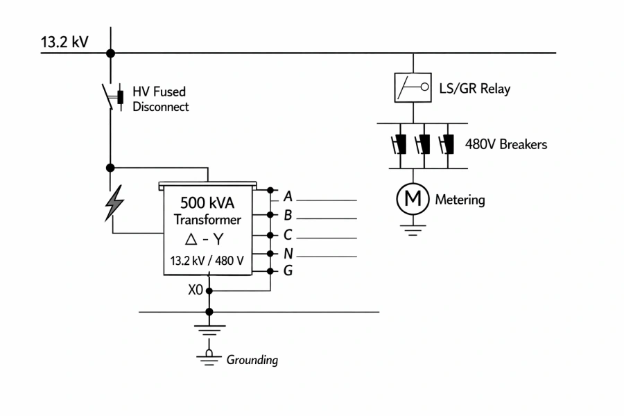
Main Components in a 500 kVA Transformer Unifilar Diagram
A typical single-line diagram for a 500 kVA transformer installation includes the following components.
1. Medium Voltage Utility Supply
The power system begins with a utility feeder, typically between 12 kV and 35 kV.
2. High Voltage Disconnect Switch
This device allows operators to isolate the transformer for maintenance or emergency shutdown.
3. Surge Arresters
Surge arresters protect the transformer from:
-
Lightning strikes
-
Switching surges
-
Transient overvoltage
4. High Voltage Protection
Protection devices may include:
-
Current limiting fuses
-
Load break switches
-
Protective relays
5. 500 kVA Transformer
Typical specification:
-
Capacity: 500 kVA
-
Primary voltage: 13.2 kV
-
Secondary voltage: 480Y/277 V
-
Connection: Delta–Wye
-
Frequency: 60 Hz
6. Grounding System
The transformer neutral point (X0) is connected to the grounding electrode system, ensuring electrical safety and fault protection.
7. Low Voltage Distribution Panel
After the transformer, power flows into a low-voltage switchboard or panel, which distributes electricity through:
-
Circuit breakers
-
Motor control centers
-
Lighting panels
-
Building loads
Where 500 kVA Transformers Are Commonly Used
A 500 kVA distribution transformer is widely used in medium-size power distribution systems.
Commercial Buildings
-
Office complexes
-
Hotels
-
Shopping malls
-
Hospitals
Industrial Facilities
-
Manufacturing plants
-
Warehouses
-
Food processing facilities
Proyectos de infraestructuras
-
Utility distribution networks
-
Renewable energy projects
-
Municipal infrastructure
Because of its balanced capacity, the 500 kVA transformer offers efficient power distribution without oversizing the system.
Design Standards for Transformers Used in the United States
Transformers installed in the United States must comply with several industry standards.
Major Standards
-
ANSI C57 series
-
IEEE transformer standards
-
DOE energy efficiency requirements
-
NEMA transformer specifications
These standards regulate:
-
Efficiency levels
-
Insulation requirements
-
Testing procedures
-
Safety performance
Manufacturers exporting to the U.S. market must ensure their transformers meet these specifications.
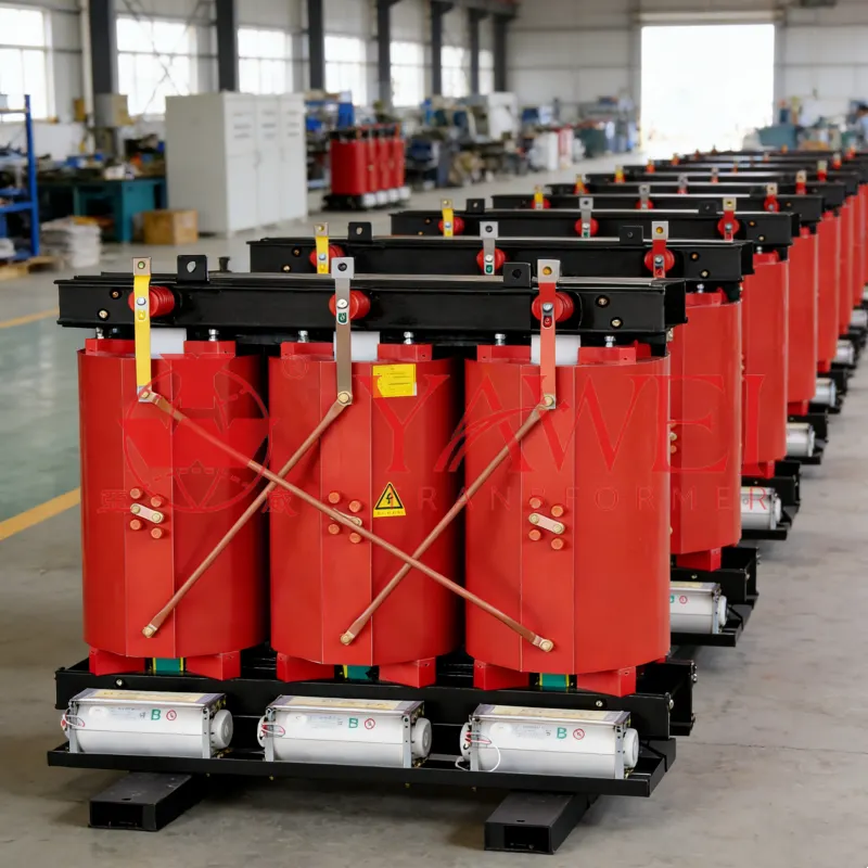
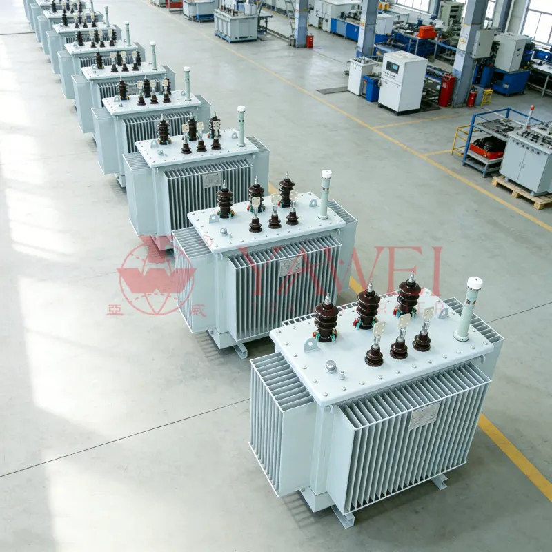
500 kVA Distribution Transformers from Yawei Transformer
Transformador Yawei is a professional manufacturer specializing in medium-voltage and distribution transformers for international markets.
Our transformer solutions include:
-
500 kVA pad mounted transformers
- 500 KVA dry type transormer
-
custom voltage configurations
Typical export specifications include:
-
Primary voltage: 12.47 kV / 13.2 kV / 13.8 kV / 34.5 kV
-
Secondary voltage: 480Y/277V / 208Y/120V
-
Frequency: 60 Hz
-
Cooling type: ONAN
-
Standards: ANSI / IEEE / DOE efficiency
With advanced manufacturing facilities and strict quality control, Yawei Transformer provides reliable transformer solutions for utilities, EPC contractors, and industrial power projects worldwide.
Frequently Asked Questions (FAQ)
What is a transformer unifilar diagram?
A transformer unifilar diagram is a simplified electrical drawing that represents a three-phase power system using a single line. It shows the connections between transformers, switchgear, protection devices, and loads.
What voltage is typical for a 500 kVA transformer in the United States?
Typical voltage ratings include:
-
Primary: 12.47 kV or 13.2 kV
-
Secondary: 480Y/277 V
This configuration is widely used in commercial and industrial facilities.
What does Delta–Wye mean in a transformer?
Delta–Wye refers to the transformer winding configuration where the primary side uses a delta connection and the secondary side uses a wye (star) connection, providing a grounded neutral point.
Is 500 kVA a common transformer size?
Yes. A 500 kVA transformer is a common size used for medium commercial buildings, factories, and utility distribution networks.