
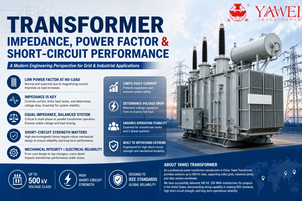
A Modern Engineering Perspective for Grid & Industrial Applications
Power transformers are not only energy conversion devices—they are dynamic electrical systems whose behavior changes significantly under no-load, load, and fault conditions. Understanding impedance, power factor, and short-circuit performance is essential for designing stable and efficient power networks.
1. No-Load Operation: Why Transformers Still Consume Power
Even when a transformer has no connected load, it is never completely idle. A small current, known as the no-load current or excitation current, still flows in the primary winding.
Typically, this current is about 3–5% of the rated current, and its primary function is to:
- Establish magnetic flux in the transformer core
- Sustain electromagnetic induction required for voltage transformation
Under no-load conditions:
- The circuit behaves predominantly inductive
- Reactive power dominates
- Real power consumption is limited to core losses (hysteresis + eddy current losses)
As a result, transformers at no-load naturally exhibit a low power factor, which is expected behavior rather than inefficiency.
2. Power Factor: From Reactive Energy to Useful Output
Power factor (PF) describes how effectively electrical power is converted into useful work.
In simplified terms:
- Low PF → high reactive power → inefficient energy utilization
- High PF → more real power → efficient system operation
Transformer Behavior Across Load Conditions
- No-load condition:
Power factor is very low due to dominant magnetizing current - Partial load:
Resistive (real power) component increases - Full load:
Power factor approaches unity as the system becomes more balanced
This transition is a normal and expected characteristic of transformer operation.
3. Transformer Impedance: A Critical Design Parameter
Transformer impedance is one of the most important engineering parameters in power system design.
It consists of:
- Resistance (R): responsible for copper losses
- Reactance (X): responsible for phase shift and current limitation
Why Impedance Matters
1. Fault Current Limitation
Without sufficient impedance, short-circuit currents would reach extremely high levels, risking catastrophic equipment failure.
2. Voltage Regulation
Impedance directly affects voltage drop between no-load and full-load conditions.
3. System Stability in Parallel Operation
In multi-transformer systems, impedance balance ensures:
- Even load sharing
- Stable voltage distribution
- Prevention of overheating or circulating currents
Special Engineering Consideration
In some distribution systems (such as mixed kVA configurations), transformers may have different power ratings. However:
👉 Impedance values must still be closely matched
to maintain stable phase behavior and load balance.
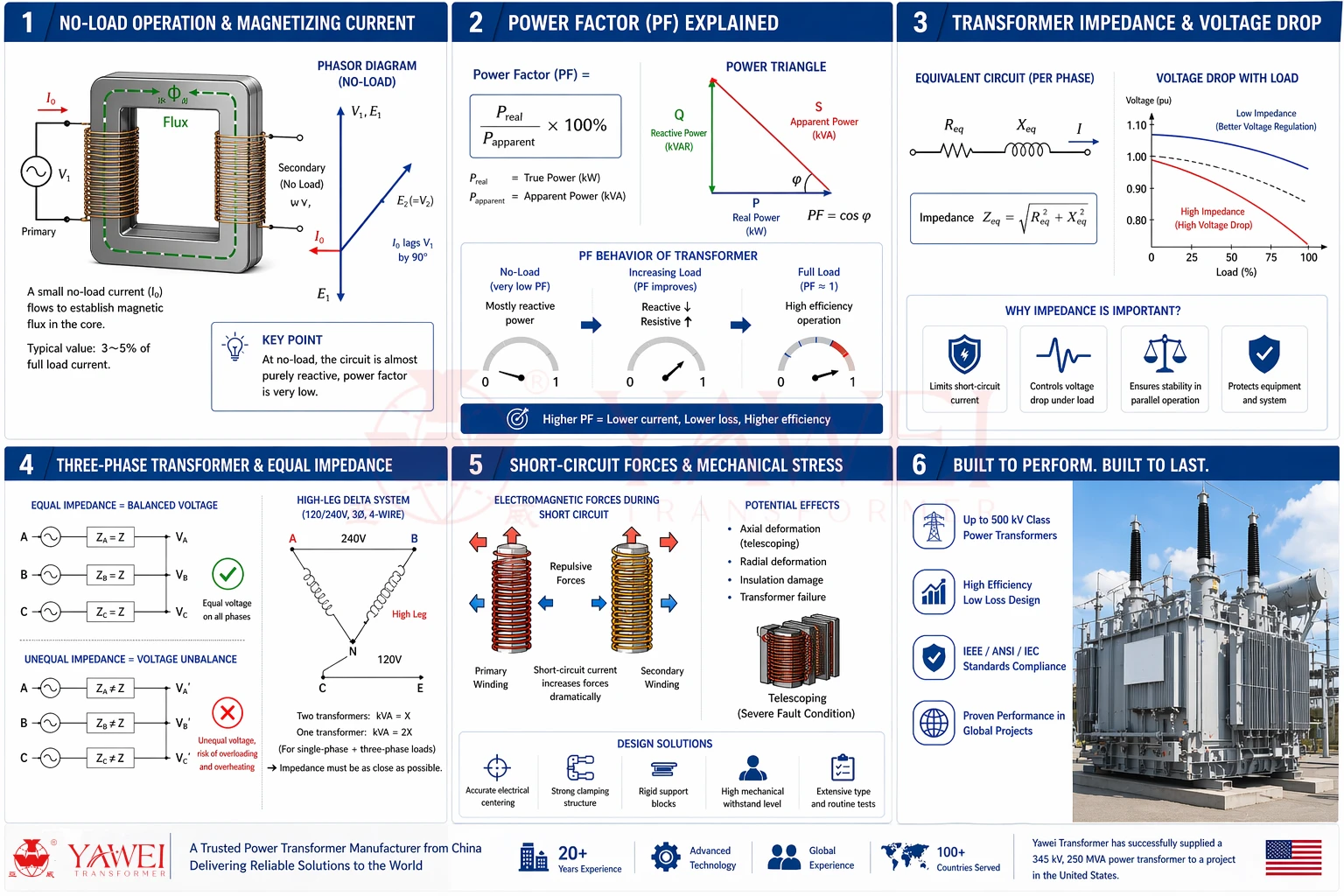
4. Short-Circuit Performance: Mechanical Stress Beyond Electricity
Short-circuit conditions are among the most extreme operating scenarios for a transformer.
What Happens During a Fault?
- Extremely high current flows through windings
- Intense electromagnetic forces are generated
- Windings experience strong radial and axial mechanical stress
These forces can lead to:
- Winding deformation
- Axial displacement
- Insulation damage
- Permanent mechanical failure
5. Engineering Design for Short-Circuit Strength
To withstand fault conditions, transformers are designed with:
- High mechanical clamping strength
- Reinforced winding structures
- Precision-aligned electrical centers
- Robust insulation spacing systems
For large power transformers, short-circuit withstand capability is a mandatory design and test requirement, not an optional feature.
6. Tap Changers and Mechanical Stress Considerations
When transformers are equipped with on-load tap changers (OLTC), especially on the HV side, the electrical center of the winding may shift during operation.
This can introduce:
- Slight asymmetry in flux distribution
- Increased mechanical stress under fault conditions
- Additional design complexity for winding support
Therefore, tap changer integration must always consider short-circuit mechanical coordination.
7. Key Engineering Takeaways
- No-load current is normal and necessary for transformer operation
- Power factor naturally improves as load increases
- Impedance is essential for fault protection, voltage control, and system stability
- Balanced impedance is critical in parallel and multi-phase systems
- Short-circuit performance is fundamentally a mechanical design challenge, not just an electrical one
In transformer engineering, electrical performance and mechanical strength are inseparable.
About Yawei Transformer
As a professional power transformer manufacturer, Transformator Yawei designs and produces solutions up to 500 kV class for global utility, industrial, and infrastructure applications.
We have delivered high-performance units including 345 kV, 250 MVA power transformers for North American projects, meeting strict IEEE standards with strong short-circuit withstand capability, high efficiency, and long-term operational reliability.