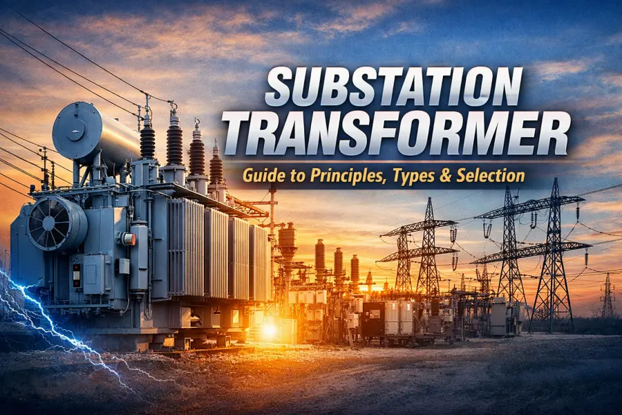
Introduction: Why Substation Transformers Are the Backbone of Power Systems
In every modern power system—whether it serves cities, industrial zones, mines, data centers, or renewable energy plants—substations play a critical role. And at the heart of every substation lies one piece of equipment that determines efficiency, safety, and long-term reliability:
the substation transformer.
From power generation to transmission and final distribution, electricity must be converted between different voltage levels. This voltage transformation is not optional—it is essential. A failure or poor selection of a substation transformer can result in large-scale outages, equipment damage, or millions of dollars in economic losses.
That is why substation transformers are often:
-
The most expensive asset in a substation
-
The most technically demanding equipment
-
The longest-life component, designed for 20–30 years of continuous operation
This article is written as a practical, engineering-oriented guide. Whether you are a project engineer, EPC contractor, utility buyer, or industrial investor, this guide will help you understand substation transformers from fundamentals to real-world selection and procurement.
What Is a Substation Transformer?
A substation transformer is a power transformer installed in electrical substations to convert voltage levels within transmission and distribution networks.
Its main functions include:
-
Stepping up voltage for long-distance power transmission
-
Stepping down voltage for regional or industrial distribution
-
Isolating different sections of the power system
-
Supporting system stability and fault management
Substation transformers are widely used in:
-
Power generation plants
-
Transmission substations
-
Industrial substations
-
Renewable energy grid-connection stations
-
Utility and national grid infrastructure
Substation Transformer vs Distribution Transformer: Key Differences
Although both are power transformers, substation transformers and distribution transformers are fundamentally different in design philosophy and application.
| Aspect | Substation Transformer | Distribution Transformer |
|---|---|---|
| Typical Capacity | ≥ 1 MVA (often 10–500 MVA) | ≤ 2500 kVA |
| Voltage Level | Medium, High, Extra-High Voltage | Medium to Low Voltage |
| 应用 | System-level voltage conversion | End-user power supply |
| Design Focus | Reliability, system stability | Efficiency, cost |
| Standards | IEC, IEEE, ANSI, GB | IEC, ANSI (simplified) |
| Investment Impact | Core substation asset | Auxiliary system component |
In short:
Substation transformers are designed for system reliability, not just energy efficiency.
Working Principle of Substation Transformers
At its core, a substation transformer operates based on electromagnetic induction. However, large power transformers are far more complex than textbook examples.
Simplified Operating Process:
-
AC voltage is applied to the high-voltage winding
-
Alternating magnetic flux is generated in the transformer core
-
The magnetic flux induces voltage in the secondary winding
-
Voltage level changes according to the winding turns ratio
Why Substation Transformers Are More Challenging:
-
Extremely high voltage stress (up to hundreds of kilovolts)
-
Very large currents
-
Continuous long-term operation
-
Exposure to short-circuit forces, lightning impulses, and grid disturbances
This requires advanced engineering in:
-
Core design
-
Winding structure
-
Insulation systems
-
Cooling technology
Main Types of Substation Transformers
1. Classification by Cooling Method
Oil-Immersed Substation Transformers (Most Common)
-
Cooling medium: mineral oil or ester oil
-
Advantages: excellent heat dissipation, long service life
-
Typical cooling modes: ONAN, ONAF, OFAF
-
Applications: transmission and distribution substations worldwide
Dry-Type Substation Transformers
-
Cooling medium: air or epoxy resin
-
Advantages: fire-resistant, low maintenance
-
Limitations: capacity and voltage constraints
-
Applications: indoor substations, urban or fire-sensitive areas
For large-capacity substations, oil-immersed transformers remain irreplaceable.
2. Classification by Application
-
Step-up transformers (power plants, renewable energy)
-
Step-down transformers (transmission to distribution)
-
Interconnecting transformers (grid coupling)
-
Station service transformers (auxiliary power supply)
3. Classification by Winding Structure
-
Two-winding transformers
-
Three-winding transformers
-
Autotransformers (commonly used in EHV systems)
Key Technical Parameters of Substation Transformers
Understanding these parameters is essential for correct selection and safe operation.
1. Rated Power (MVA)
Typical ratings include:
5, 10, 20, 31.5, 40, 50, 63, 100, 150, 250 MVA
Selection principle:
-
Rated capacity ≥ maximum load × 1.2–1.3
-
Allow margin for future expansion
Incorrect capacity selection may lead to:
-
Chronic overloading
-
Reduced service life
-
Increased maintenance costs
2. Rated Voltage and Voltage Ratio
Examples:
-
110 / 35 kV
-
220 / 110 / 35 kV
-
35 / 10 kV
Must clearly define:
-
System voltage
-
Tapping range
-
Connection group (Y, Δ)
-
Neutral grounding method
3. Impedance Voltage (%)
-
Limits short-circuit current
-
Impacts system protection coordination
-
Must be matched with grid design requirements
This parameter should always be confirmed with the utility or system designer.
4. Cooling Method Code
Common cooling modes:
-
ONAN: Oil Natural Air Natural
-
ONAF: Oil Natural Air Forced
-
OFAF / OFWF: Large-capacity transformers
Cooling design directly affects:
-
Load capability
-
Thermal aging
-
Transformer lifespan
Why Substation Transformer Prices Differ So Much
Many buyers ask:
“Why do two transformers with similar parameters have a 20–50% price difference?”
The answer lies in manufacturing quality and engineering details.
Key Cost Drivers:
1. Core Material and Design
-
High-grade grain-oriented silicon steel
-
Low-loss core structure
-
Precision stacking and clamping
2. Winding Technology
-
Continuously Transposed Conductors (CTC)
-
High short-circuit mechanical strength
-
Optimized electromagnetic balance
3. Insulation System
-
High-quality insulation paper
-
Controlled oil-paper aging performance
-
High dielectric margins
4. Drying and Oil Filling Process
-
Vacuum drying technology
-
Moisture content control
-
Direct impact on service life
A substation transformer is not a “commodity product”—it is an engineered system.
Common Failures and Preventive Measures
Typical Failures:
-
Insulation degradation
-
Winding deformation
-
Oil gas generation
-
Partial discharge
Preventive Measures:
-
Correct design and selection
-
Reasonable loading
-
Regular oil analysis (DGA)
-
Online monitoring systems
Early prevention significantly reduces life-cycle costs.
How to Select the Right Substation Transformer for Your Project
Step 1: Define Project Application
-
Utility grid
-
Industrial facility
-
Renewable energy plant
Step 2: Confirm Key Parameters
-
Rated power (MVA)
-
Voltage levels
-
Cooling method
Step 3: Identify Applicable Standards
-
IEC
-
IEEE / ANSI
-
National grid requirements
Step 4: Choose an Experienced Manufacturer
-
Proven substation transformer references
-
Engineering support capability
-
Reliable quality control
Lack of experience in large substation projects is a major risk.
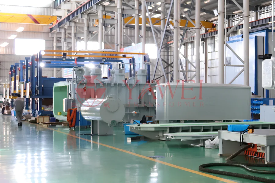
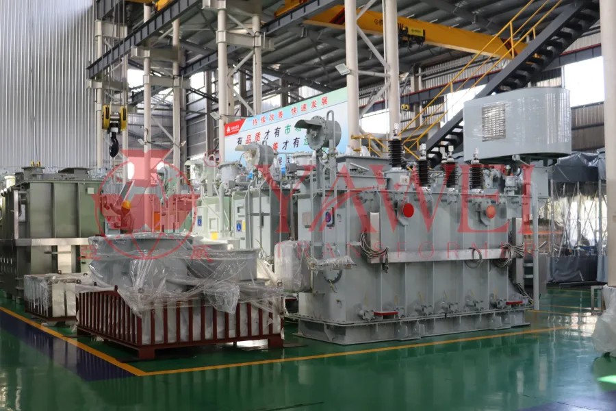
Why Global Clients Choose Yawei Transformer
As a professional power transformer manufacturer, Yawei Transformer focuses on substation-level transformer solutions for global markets.
Our strengths include:
-
Substation transformers from 5 MVA to 500 MVA
-
Voltage levels up to extra-high voltage classes
-
Compliance with IEC, IEEE, ANSI standards
-
Custom engineering for grid, industrial, and renewable projects
-
Strict routine and type testing before delivery
We do not simply manufacture transformers—we deliver long-term power reliability solutions.
Final Thoughts: A Substation Transformer Is a 30-Year Investment
In power systems, substation transformers are not consumables—they are strategic assets.
A well-designed and correctly selected transformer means:
-
Decades of stable operation
-
Lower maintenance and operating costs
-
Reduced outage and failure risks
If you are planning or sourcing a substation transformer, our engineering team is ready to support you with:
-
Free technical consultation
-
Project-specific transformer design
-
Fast and professional quotation response
Contact Yawei Transformer today to ensure your power project starts with the right foundation.